3 Terminal Block Connection Diagram EVU and Terminal Block Designer
The following three examples explain how settings in the Terminal Block Designer are shown in the Terminal Block Diagram EVU.
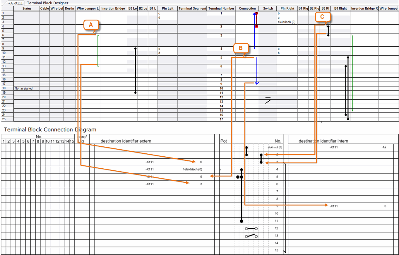
Example 1:
The relationship between Terminal Block Designer and Terminal Block Diagram EVU
Case A: A wire jumper: this is the connection between two terminals of a terminal block. In the Terminal Block Diagram EVU, it is shown as a destination designation (internal or external) and not graphically.
Example: In the Terminal Block Designer there is a wire jumper left built between the terminals 3 and 6 of the terminal block. In the Terminal Block Diagram EVU, this wire jumper is represented as "External destination designation," where terminal 3 is referred to terminal 6 and vice versa.
Case B: A mixed wire jumper right/left: this is the connection between two terminals of a terminal block. In the Terminal Block Diagram EVU, it is shown as a destination designation (internal or external) and not graphically.
In the example in the Terminal Block Designer a wire jumper is displayed, connected to terminal 5 on the left side and to terminal 9 on the right side. In the Terminal Block Diagram EVU, this wire jumper may be found at terminal 5 at "target designation extern" as reference to terminal 9. At terminal 9 at "target designation intern," a reference to terminal 5 may be found.
Case C: If a jumper is defined in an accessory slot, it is shown in the terminal block connection diagram as a jumper in one of the accessory columns.
Example: In the Terminal Block Designer, a jumper is defined in the accessory slot B3 right. In the Terminal Block Diagram EVU, it is shown as a jumper.
Example 2:
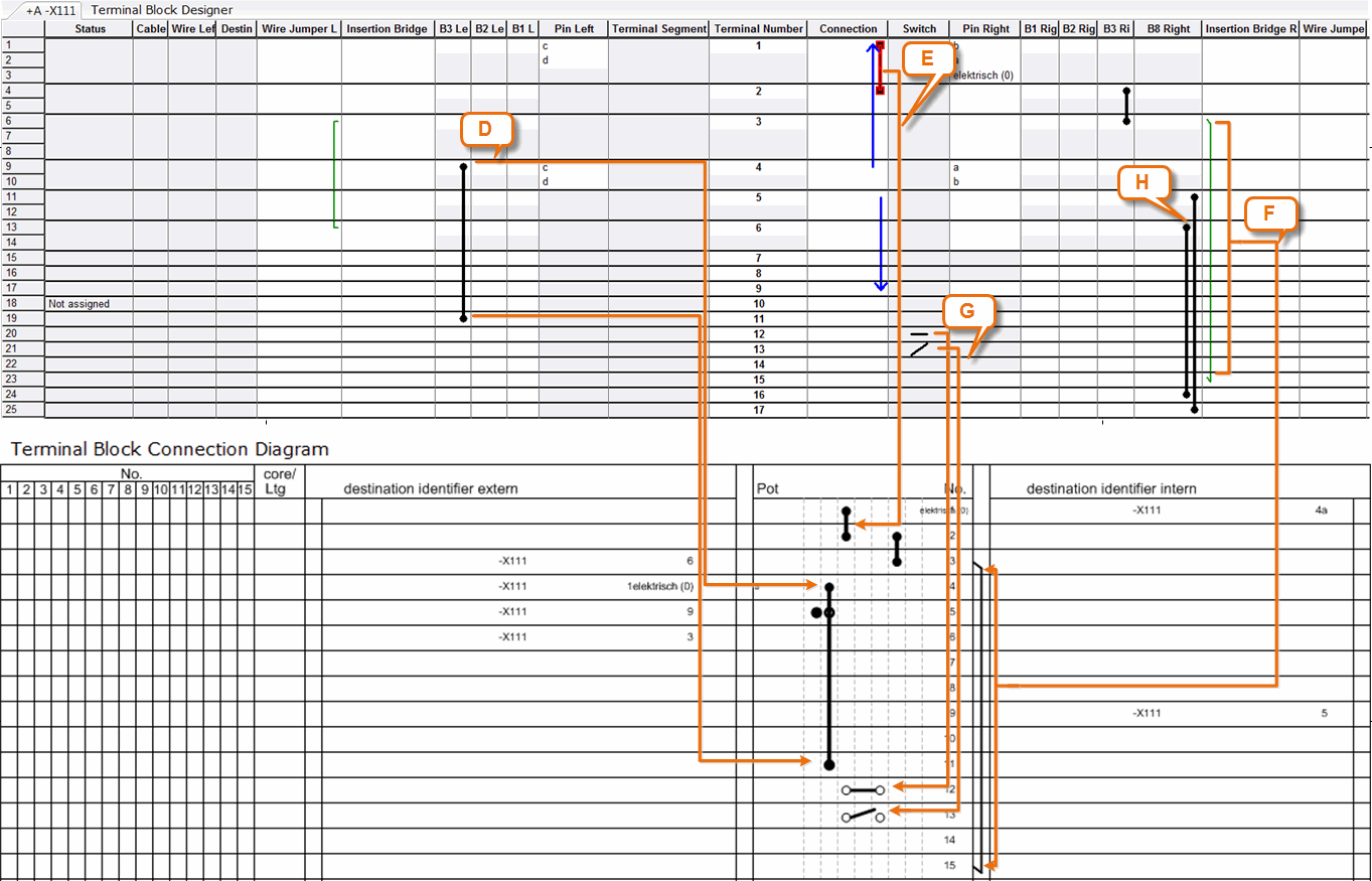
The relationship between Terminal Block Designer and Terminal Block Diagram EVU with accessories
Case D: A fixed bridge is defined as material bridge in a slot of accessory. This bridge is represented in the Terminal Block Diagram EVU as a fixed bridge with the respective shape.
In this example, there is in the Terminal Block Designer a fixed bridge (material bridge) in the slot of accessory B3 left. In the Terminal Block Diagram EVU, it will be represented as fixed bridge with the shape EXBDGO_LI of the material bridge.
Case E: The unspecified connection in the Terminal Block Designer is shown in the Terminal Block Diagram EVU as jumper, if the terminals are located sequentially on the terminal block and if they have the same type and potential.
In the example, there is an unspecified connection between the terminals 1 and 2. In the Terminal Block Diagram these are shown as jumpers.
Case F: If an insertion bridge (left or right) is defined in the Terminal Block Designer, it is shown as a jumper (external or internal) in the Terminal Block Diagram EVU.
In the example, there is an insertion bridge right between the terminals 3 and 15. In the Terminal Block Diagram EVU it is shown as an internal jumper.
Case G: In the Terminal Block Designer 2 terminals are defined as switches. They are represented in the terminal diagram with the respective symbols.
In the example, terminal 12 is a closed terminal switch (attribute switch normally closed is marked). Terminal 13 is a terminal switch.
Case H: Unspecified connections for which the option Not shown in diagram was specified in the context menu, are automatically moved to this column. These connections are not shown in the terminal diagram. The connection is stored as bridge in the project. At the bridge, the Boolean attribute Suppress Bridge in Terminal Block diagram is marked and the attribute Jumper Specification is set to Bridge not Represented.
In the example, the corresponding connections are located between the terminals 5 and 17 and the terminals 6 and 16.
Example 3:
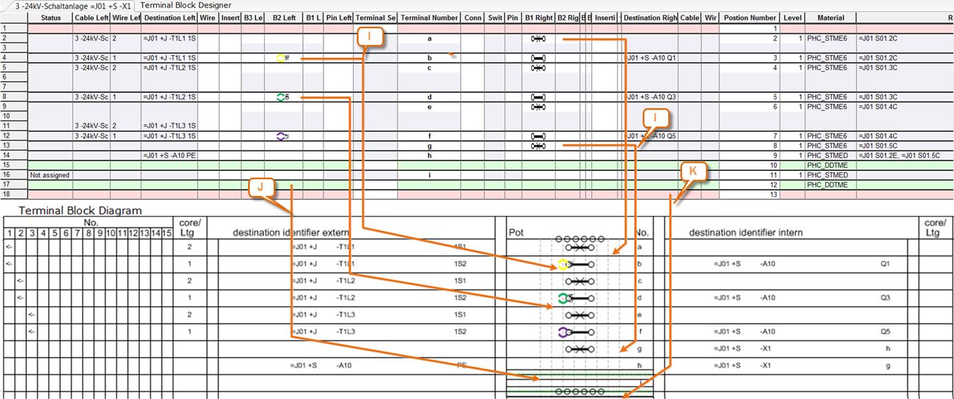
The relationship between Terminal Block Designer and Terminal Block Diagram EVU with accessories
The shapes shown in the Terminal Block Designer and Terminal Block Diagram EVU are defined in the Engineering Base Explorer in Terminal accessories (Button Stencils / folder Graphics Toolbox.
|
|
If there is no material (with Master-Shape definition in Specifications) assigned to the accessory or if there is no Master-Shape defined in Specifications, the end clamps or end covers are not shown in the Terminal Block Diagram EVU.
|
Case I: Material is defined in an accessory slot. If there are multiple materials assigned to the accessory slots of one terminal, the shapes are displayed overlapping in the Terminal Block Diagram EVU.
In the example, there are multiple materials defined in the accessory slots B2 left and B1 right in the Terminal Block Designer. In the Terminal Block Diagram EVU, they are also displayed overlapping.
Case J: An end cover is defined in the Terminal Block Designer. It is also shown in the Terminal Block Diagram EVU.
In the above example, there are end covers after terminals h and i. In the Terminal Block Diagram EVU they are displayed with the defined Master-Shapes.
Case K: An end clamp is defined in the Terminal Block Designer. The end clamp is also displayed in the Terminal Block Diagram EVU, if there is a Master-Shape predefined.
In the above example an end clamp is defined before the terminal a and after the terminal i. In the Terminal Block Diagram EVU they are displayed with the defined Master-Shapes.
Example 4:
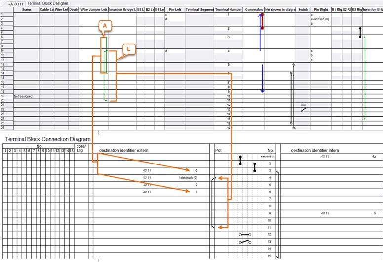
The relationship between Terminal Block Designer and Terminal Block Diagram EVU
Case A: A wire jumper; this is the connection between two terminals of a terminal block. In the Terminal Block Diagram EVU, it is displayed as a destination designation (internal or external) and not graphically. This case has already been described in Example 1.
Case L: A graphical wire jumper is displayed in the column wire jumper (left or right) in the Terminal Block Designer. In the Terminal Block Diagram EVU, it is shown as a jumper (external or internal).
In the example, there is a graphical wire jumper left between the terminals 4 and 11. In the Terminal Block Diagram EVU, it is shown as an external jumper.