Terminal Block Connection Diagram EVU
1 The Terminal Block Connection Diagram EVU
As every terminal diagram, the terminal block connection diagram EVU is created dynamically when it is opened. Thus the terminal diagram represents the current project status.
The Terminal Block Connection Diagram 15er Matrix EVU DIN has two main areas:
1. Information about the connections to and from the terminal, wiring material and terminal types.
2. Information about the terminal, with terminal number (as used in the Explorer), a terminal matrix with 15 connections, internal and external slots of the terminal and the internal and external destination designations.
|
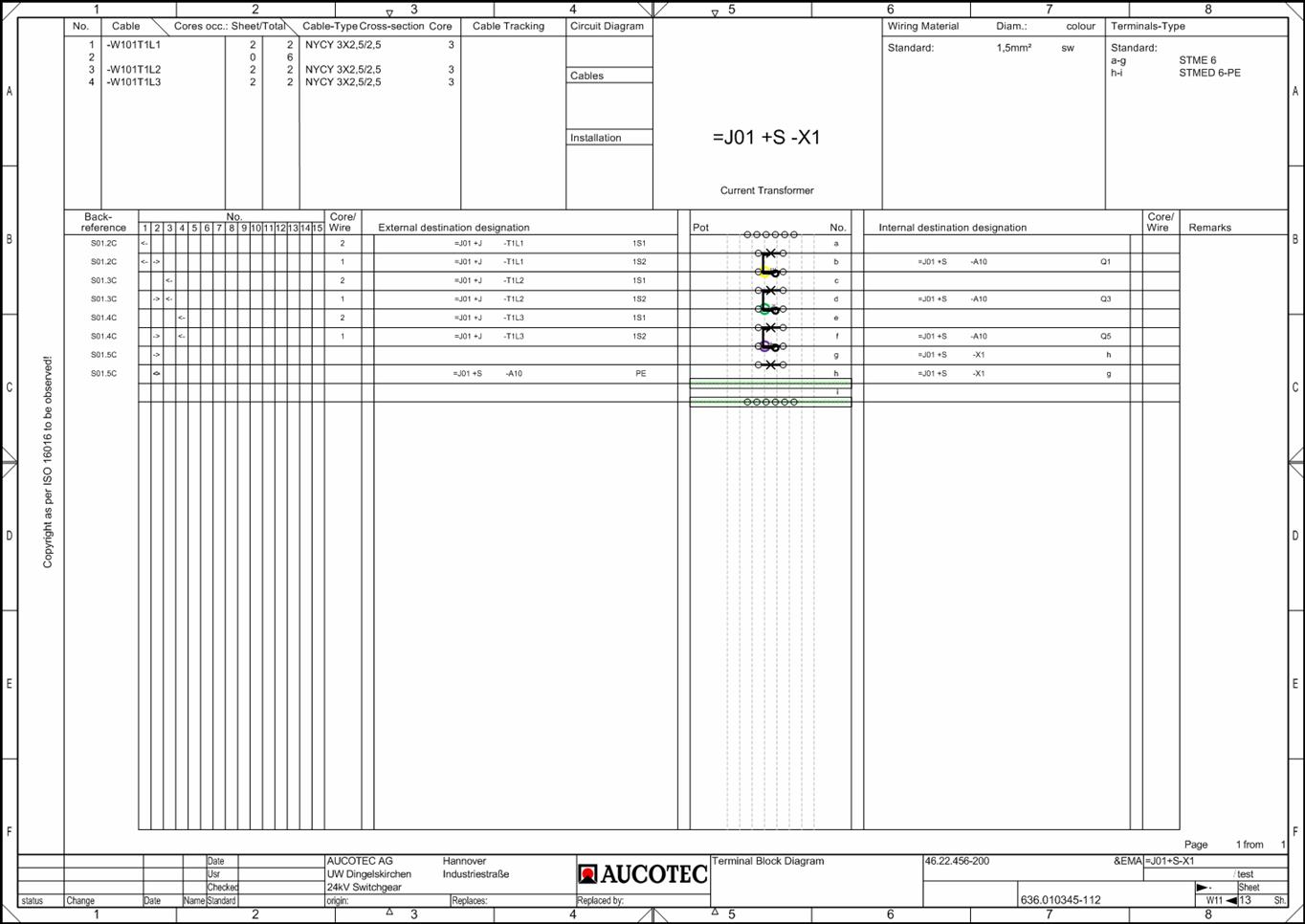
Terminal Block Connection Diagram EVU |
Area of cable information
|
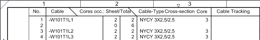
Area of cable information |
Example: Cable number 1 has 3 cores, two cores are occupied, both in this sheet.
|
Column |
Meaning/Content |
|
No. |
Refers to the cable number in the terminal matrix, number of 1 – 15 for each cable used. |
|
Cable |
Name of the cable, results from the equipment information from the catalog. |
|
Occupied cores per sheet |
Number of occupied cores on this terminal block diagram. |
|
Occupied cores total |
Number of occupied cores of this cable on all terminal block diagrams. |
|
Cable type |
Type of the cable, results from the equipment information from the catalog. |
|
Cross-section |
Cross-section of the cable, results from the equipment information from the catalog. |
|
Core |
Maximum number of cores in the cable, results from the equipment information from the catalog. |
|
Cable tracking |
Shows on which terminal diagram this cable is represented next (ascending order). |
Area of wiring material and terminal types
|
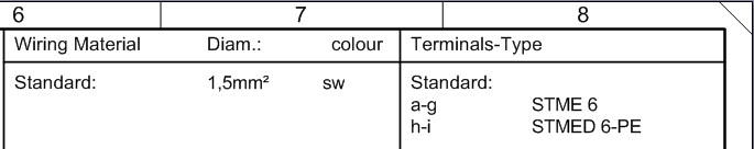
Wiring material and terminal types in the Terminal Block Connection Diagram EVU |
|
Column |
Meaning/Content |
|
Wiring Material |
· Standard: Standard material (wiring material) used for the internal wiring of the terminal block. · Pos: Wiring material used for the internal or external wiring of the terminal block. The position number of the used wiring material is shown in the Terminal Block Diagram EVU in the column core/wire (internal or external). The entries in the wiring material table are sorted by wire type, diameter and color. If the wiring material is used, either internal or external, it is not shown in the terminal matrix. |
|
Diameter |
Diameter of the wiring material |
|
Color |
Color of the wiring material |
|
Terminal-Type |
· Standard: Standard terminal type. If the attribute Standard Terminal Type is predefined at the terminal strip and Terminal Summary Options=1 is set in the terminal diagram template, the predefined standard terminal is displayed. If either the attribute Standard Terminal Type is empty or the switch Terminal Summary Options <1> is set the terminal diagram template, the terminal most often entered is entered as the standard terminal type. · 1 - xx: Terminal type on position 1 -xx The terminal types of the terminal block are displayed with their position. |
General Information on the terminal block
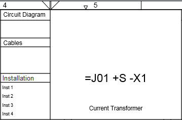
General information on the terminal block in the Terminal block Diagram EVU
|
Column |
Meaning/Content |
|
Circuit Diagram |
Reference to the corresponding circuit diagram |
|
Cables |
Reference to the corresponding cable list |
|
Installation |
Mounting hints are taken from the attributes Installation Instruction 1 – Installation Instruction 4 of the terminal block. |
|
=J01 +S -X1 |
Terminal block for which the terminal block diagram was created. The representation is controlled in the terminal diagram template by the attribute Hide Terminal Block Location. |
Information about the terminal structure
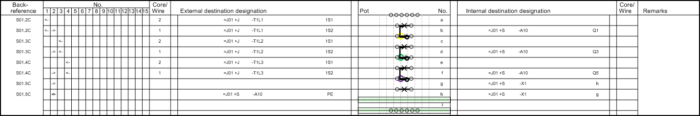
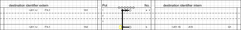
Terminal structure in the Terminal Block Connection Diagram EVU
|
Column |
Meaning/Content |
|||
|
Back-reference |
Drawing on which the terminal is represented. |
|||
|
No. |
Cable number; under this number further information about the cables can be found in the cable information area
In the previous example, each of the terminals 1, 3 and 4 is connected with 2 cores to the external side of the terminal. |
|||
|
Core/Wire |
· Core number (wire) for internal and external destinations. Position number of the used wiring material, taken from the wiring material table at the top of the Terminal Block Diagram EVU (for internal or external destinations). |
|||
|
External/Internal destination designation |
External or internal destination of the terminal. |
|||
|
Remarks |
Remarks about the terminal are entered here; for instance, the levels of a multi-level terminal blocks. |
|||
|
Pot |
Associated potential |
|||
|
in between |
Slots of accessory |
|||
|
No. |
Terminal Number |
If the attribute Pin Ordering is marked at the terminal, all pins of the terminal are displayed irrespective of whether an entry is made under the Pin Designation of the pin or whether the pin has an allocation. The pins are displayed next to the assigned potential (for external pins) and next to the terminal number (for internal pins).
Pins with the pin position = 0 are excluded from this rule.
For terminals with more than two pins, graphical wire bridges and insertion bridges are displayed on the associated pins.
|
The terminal structure with the set pin ordering at terminal a |